
CNC Machining
Low-Volume CNC Machined Aluminum Housings: How to Specify O-Ring Grooves and Sealing Faces
A practical RFQ guide for low-volume CNC machined aluminum housings with static O-ring seals: define the gland, mating face, finish, inspection, and leak test before quoting.
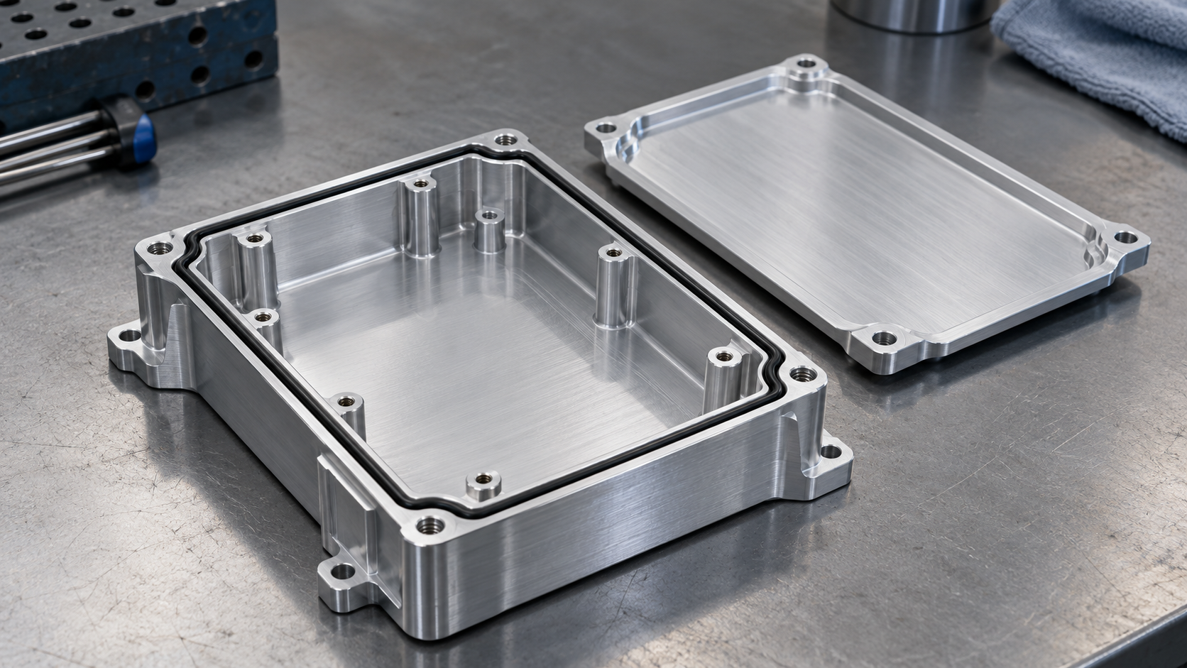
A sealed housing can look perfectly machined and still fail a leak test. The outside dimensions may be within tolerance while a shallow O-ring groove, a bowed lid, a scratch across the seal path, or an uncalled-out coating changes how the joint closes. In a low-volume run, there may be no time or budget for several rounds of tooling changes. The most effective starting point is a drawing and RFQ that describe the assembled seal, not merely the visible shape of the aluminum part.
This guide is for engineers buying CNC-machined aluminum housings, covers, and enclosures with a static face O-ring seal. It focuses on what to specify, what to ask the machine shop to inspect, and which decisions belong to the seal designer. It is not a substitute for a seal manufacturer's gland calculation or a validated leak-test specification.
Define the sealing duty before requesting a machining quote
“Waterproof housing” is not enough information to price or validate a part. A shop needs to know what the assembly must contain or exclude and how it will be tested. Start with the operating medium (water, oil, air, another gas, or a chemical), pressure or vacuum range, temperature range, expected exposure duration, and whether the joint will be opened for service. State whether pressure acts from inside the housing or outside it. These inputs affect the seal material, gland geometry, and which groove diameter is controlled. Parker's O-Ring Handbook, Section 4.3, explicitly distinguishes face-gland dimensioning for pressure acting outward versus inward.
Also define the required acceptance test. A pressure-decay test, immersion test, and helium leak test do not establish the same thing. The RFQ should name the method, test pressure or vacuum, stabilization and hold times, allowable leakage or pressure change, and whether testing is done before or after surface treatment. If these are still being developed, label them to be validated rather than silently treating “leak-tight” as a machining tolerance.
If the housing mates with a customer-supplied lid, ask for the lid drawing or a controlled interface model. The seal is created by the two mating parts, fasteners, and O-ring together. A beautiful groove in one component cannot compensate for an unknown opposing face or insufficient joint stiffness.
Put the O-ring gland on the controlled drawing
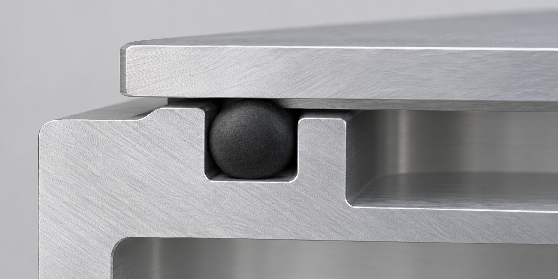
Conceptual cross-section before final closure; use the selected seal manufacturer's dimensions for the actual gland.
The groove is a functional feature, not a cosmetic pocket. Identify the chosen O-ring by manufacturer, material/compound, size, and revision, or provide enough service conditions for the seal specialist to select it. Specify the final gland dimensions and tolerances derived from the actual selected seal and its operating conditions. Do not copy a generic groove depth from a search result: O-ring cross-section tolerance, squeeze, stretch, gland fill, thermal expansion, and pressure direction all matter. Parker's face-seal design chart and instructions are a useful primary reference, but the values must be checked for the particular assembly.
At minimum, make the following legible in both the model and 2D drawing:
| Feature | What the RFQ should define | Why it matters |
|---|---|---|
| Seal identity | O-ring size, compound, supplier, or an explicitly open selection | The gland cannot be validated without the actual seal |
| Groove planform | Controlled inside or outside diameter, path, corner geometry, and pressure direction | Controls seal position and available contact area |
| Groove section | Depth, width, bottom geometry, edge breaks, and tolerances | Determines squeeze and avoids installation damage |
| Mating interface | Lid and housing contact areas, locating scheme, fastener pattern, and compression stop if used | Controls closure and variation around the perimeter |
| Surface requirement | Which exact faces and groove regions need a stated texture and no transverse damage | Avoids ambiguity between cosmetic and functional finishes |
| Finished condition | Whether dimensions apply before or after anodizing or another treatment | Prevents coating buildup from changing the working gland |
Do not ask the shop to “make the groove fit the O-ring” while leaving all gland dimensions open. That transfers a seal-design decision into manufacturing without a measurable acceptance criterion. Conversely, avoid specifying a tight tolerance on every exterior wall if only the gland, its datum relationships, and the mating face govern sealing.
Treat flatness, texture, and tool marks as separate requirements
A roughness number does not tell you whether the entire face is flat. A flatness callout does not rule out a scratch that crosses the sealing path. For a face seal, define the sealing land and mating face as named regions, then control their geometry and texture separately. Choose datums that reflect how the parts locate and clamp in the real assembly. Review the relationship between the groove floor, mating face, and any hard stops rather than checking each dimension in isolation.
Parker's handbook discusses surface finish specifically for static O-ring seals; it gives 32 microinches RMS maximum for static sealing surfaces in its design discussion and recommends 16 microinches RMS for face-type gas seals. These are handbook guidance for specified seal configurations, not universal promises that every application will seal at those values. They are also expressed as RMS, so they should not be copied into a drawing as an identical numerical Ra value. If your drawing uses current ISO profile-texture notation, ISO 21920-1:2021 covers how profile texture is indicated in technical documentation. State the parameter, limit, measurement direction or location where relevant, and acceptance method.
For CNC machining, make the sealing land a deliberate toolpath and inspection region. Ask how the shop will avoid a tool entry mark, burr, handling dent, or groove-edge defect crossing the O-ring contact band. Visual checks are useful but should not stand in for a defined profile measurement where texture is critical. NIST's introduction to surface-finish metrology explains why the measurement method and the chosen texture parameter both matter.
Thin or open-wall housings add another complication: the face may measure differently while clamped than after release. If the free-state part must seal when assembled, agree in advance how flatness will be measured, how the part will be supported, and whether a separate assembled-state test is needed. This is more actionable than requesting “high precision” without a measurement condition.
Decide how finishing changes the functional surfaces
Aluminum housings are often specified with anodizing, conversion coating, painting, or another finish for reasons unrelated to the seal. The finish may change dimensions or texture in a groove and may also introduce a masking boundary or handling risk. Do not assume the supplier will know which surfaces may be coated. Mark the groove, sealing land, threads, and any electrical-contact regions individually. State whether functional dimensions are inspected on the machined part, the finished part, or both.
There is no universal answer to “should the O-ring groove be anodized?” The decision depends on the seal system, coating process, corrosion exposure, and validated assembly. What matters to the RFQ is that the decision is explicit. If a finish is required on the sealing land, confirm with the seal designer that the specified texture and gland dimensions apply after finishing. If the land is masked, define the mask boundary so it does not cross the contact path.
Specify deburring without turning a sealing edge into an uncontrolled radius. The groove should not cut the O-ring during assembly, but excessive edge removal can alter the effective gland. Ask for an edge-break range or approved detail where this is functionally important, and confirm it against the seal manufacturer's guidance.
Build an inspection plan for a small batch
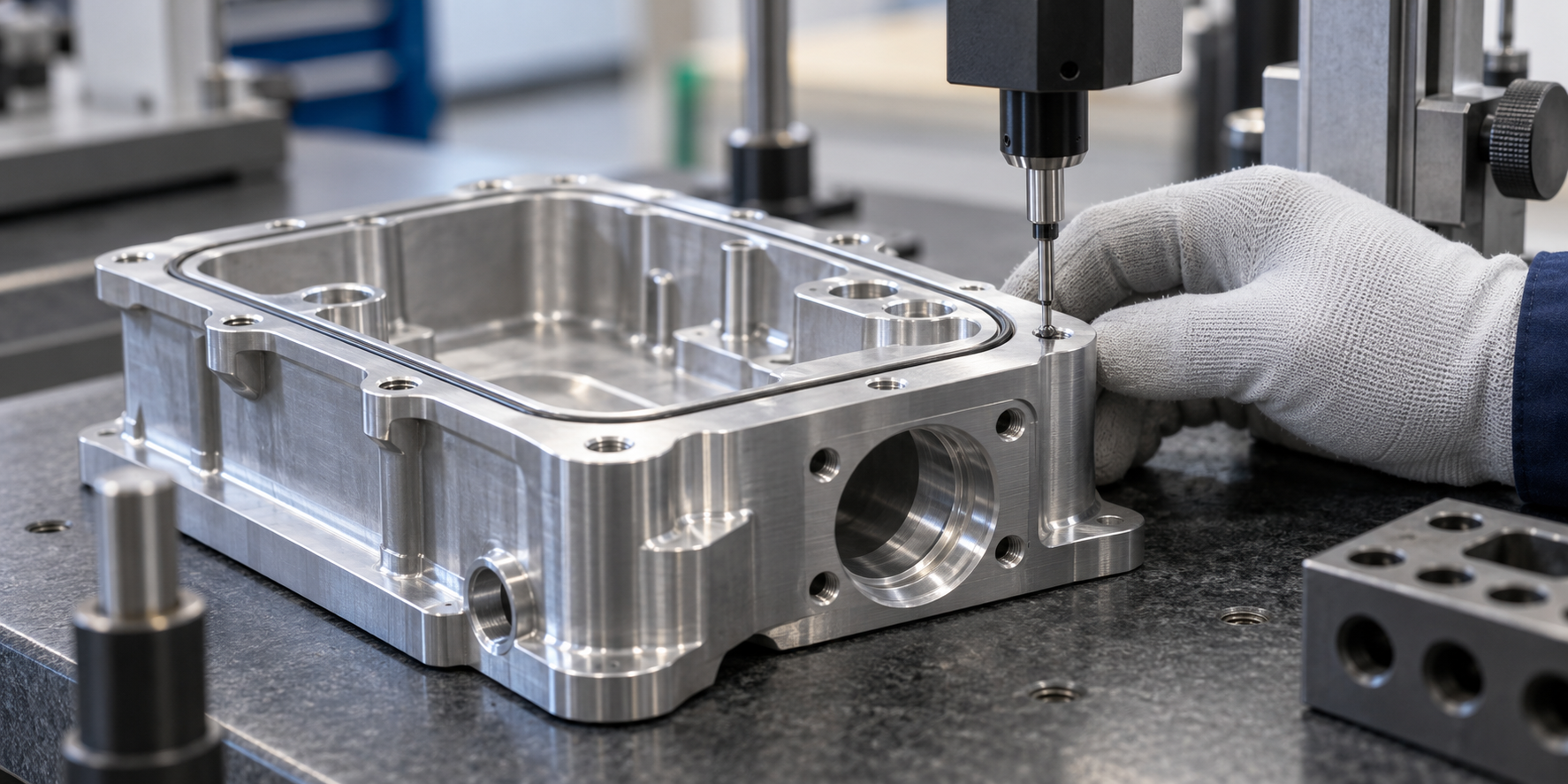
Representative inspection scene; the project-specific plan should identify each seal-critical feature and measurement method.
Low volume does not mean every feature needs a full CMM report on every piece. It means the acceptance plan should concentrate effort on the few features that could cause an expensive assembly failure. Agree on a first-piece review before the balance of the batch is machined, especially if the housing has a new groove or a revised lid interface. The first piece should be inspected in the same finished condition in which the production parts will be accepted.
An inspection plan can separate four questions:
- Is the gland right? Measure the controlled groove dimensions, including depth relative to the intended mating condition, not only an isolated pocket depth.
- Will the joint close consistently? Check the sealing-face geometry, datum relationships, and any stop or fastener-seat features that control compression.
- Is the seal path intact? Inspect for burrs, nicks, scratches, coating defects, and the specified texture on the functional land.
- Does the assembly seal? Perform the agreed functional test using representative O-rings, lids, fasteners, torque procedure, and test fixtures.
Record which dimensions are checked on every part and which are sampled. If the first article reveals a problem, distinguish a machining deviation from a design issue. For example, a groove can be within the print yet still give the wrong squeeze if the print omitted a mating-lid variation. A functional test is valuable precisely because it can expose assumptions that dimensional inspection alone cannot see.
A practical RFQ package for sealed aluminum housings
Before sending the RFQ, assemble one controlled package rather than distributing a model, a drawing, and several contradictory email notes. Include:
- A STEP model and revision-controlled 2D drawing for the housing and the mating interface.
- Quantity per release and expected repeat orders; identify any prototype-first or pilot-batch stage.
- Aluminum alloy, stock form, temper if important, and whether substitutions require approval.
- O-ring identification and the service conditions used to select it.
- Groove dimensions, datum scheme, mating-face requirements, and the finished-condition definition.
- Coating or masking instructions for the groove and sealing land.
- The required first-piece report, in-process checks, final inspection record, and test method.
- Whether the shop supplies only machined parts or also assembles and leak-tests the joint.
If a critical item is unknown, turn it into a question for the supplier instead of hiding it. “Please review whether the current groove geometry is manufacturable and quote a first-piece inspection of the sealing interface” is a productive request. “Must be waterproof” is not.
For an overview of the site's custom CNC machining approach, start there; for a project-specific review, send the drawing and service conditions through the inquiry form. Request a quote only after the acceptance criteria are clear enough that different suppliers are pricing the same job.
Frequently asked questions
Can the machine shop choose the O-ring groove size?
The shop can identify tool-access or measurement problems and suggest a manufacturable detail. Final groove sizing should be approved by the responsible design engineer using the selected seal manufacturer's data and the real operating conditions.
Is a surface-roughness callout enough to prevent leaks?
No. Roughness is one part of the interface. Flatness, scratches, groove dimensions, seal material, joint compression, and assembly practice can all affect the outcome. State how both the parts and assembled joint will be accepted.
Should a small batch be 100% leak-tested?
That depends on the failure consequence, process maturity, unit value, and the test's ability to detect the relevant leak. Agree on the sample plan and pass/fail criterion before quoting. A first-piece leak test alone does not prove every later assembly will pass.
What should be inspected before anodizing?
Any feature likely to become harder to measure or rework afterward should be considered for pre-finish inspection. The final acceptance check must still verify the dimensions and sealing surfaces in the condition defined by the drawing.
Source notes: Parker O-Ring Handbook, Section 4 and Design Chart 4-3; ISO 21920-1:2021; NIST, Introduction to Surface Finish Metrology. This article is educational guidance; the seal design and test limits must be validated for the actual assembly.